The models in question are the, the Eureka 40, Austrains 41, Auscision 43 and the On Track 82.
It all started with a mate, Craig Hill, who split the headlight from the white marker lights in the Eureka 40 and showed me what he did to achieve that which gave me the inspiration to have a go, so the 40 class is the first one I'll start with, and bar the 82 is probably the easiest to achieve so lets start with that one.
The Eureka 40 Class
The first thing changed is the wiring to the bogies, a mate (Peter Baron) mentioned that he replaced the wire to the bogies of his 40 class as he thought they where a bit thick & stiff and seemed to affect the swing of the bogies, Peter did say that once he changed the bogie wiring that the model seemed to track better, good enough for me and its simply a matter of carefully using a soldering iron and removing the existing wire and soldering in the new thinner, more flexible wire.
 |
| new thinner wires in place and old thicker replaced wires in view, the difference in size is pretty obvious |
The Eureka 40 has the lights controlled by 3 wires going to the light boards at either end, it's a (relatively) simple matter of cutting one of the traces on the light board(s) that connects the white marker lights to the headlight, thus isolating the head light from the white marker lights and soldering an extra wire to power the now isolated Headlight.
First up is a photo of the unmodified lightboard from both the front and the rear, the modification is fairly simple and is outlined in the following set of photos.
 |
| Front view of unmodified lightboard |
 | ||
| Rear view of lightboard, not particularly impressed with the colour code of the wiring | ||
The first two photos above show an unmodified lightboard, the trace that needs to be cut is on the front of the lightboard between 'P6' and LED 'L3' and the extra wire is fed through the hole above LED 'L3' and soldered to the cut trace feeding LED 'L3'
 | |
| Rear Of lightboard showing new wire (white) |
 | |
| Where the new wire is soldered to the front of the lightboard |
The 2 photos above show the modified lightboard and show the soldered extra wire on the front and the 4 wires from the rear with where the extra wire goes through the existing hole in the lightboard, I've also changed the wire colours to better meet the DCC 'standards', so the Blue wire is the common, the white is the new wire for the headlight, and the green & purple/violet wires are for the red & white markers
 | |
| Rear of 40 Cl Lightboard showing where extra wire feeds through |
 | |
| 40 Cl Lighboard showing trace to cut and where extra wire to be soldered |
The final set of 40 class lightboard photos above have drawn on them the trace that has been cut and where the extra wire is fed through and soldered onto the front of the lightboard.
Another thing that I 'improved' on the Eureka model is that there are no reflectors behind the headlights which to me looks weird, I experimented with silver paint, chrome paint (and as a side point I found a chrome paint pen name 'Matlow' which I think is brilliant) and alfoil and settled on the alfoil as it pretty well looks the part. The alfoil came from the inside of a coffee container as its a slightly thicker material than the normal store bought alfoil, I drilled a hole (about 1 - 2 mm) and then used the domed end of a knife holder to slightly dome out the alfoil to give the shape I was after. A couple of photos of the headlight show the various methods considered.
 |
| Painted reflector |
 |
| Standard Headlight - no Reflector |
 |
| Alfoil reflector |
 |
| formed alfoil reflector |
 |
| alfoil reflector and forming tool |
I also found out that the marker light suffer from light bleedthrough where the light that lights the markers bleed through the body and marker light casting, this is visible in the below photo - not a very clear photo as it was taken in low light but it does show the light bleeding through.
 |
| Light bleed through at marker lights |
I addressed this by painting the inside of the body around the marker lights in black paint followed by a coat of silver paint, this is shown in the below photo along with the alfoil reflector, or at least a test version of it

this along with a couple of coats of a red/brown mix on the marker lights themselves seems to have solved that little issue as evidenced by the photo below in similar light conditions were the bleedthrough is a lot less evident.
 |
| Light bleed through minimised at marker lights |
 | ||
| No lights showing reflector behind the headlight |
 |
| Headlight on |
 |
| White Markers Only |
 |
| Red Markers Only-note slight red in headlight |
A couple of other things I tackled whilst working on the 40 was to install sand pipes to the bogies which are simply some .5mm brass wire bent to shape and glued in place into holes drilled into the chassis and fixing the buffers where the spring clip holding the buffer shank in place of which one was nowhere to be seen by replacing said lost spring clip with a thin piece of wire soldered to the shank, the photos below probably explain it a lot better than I can type it.
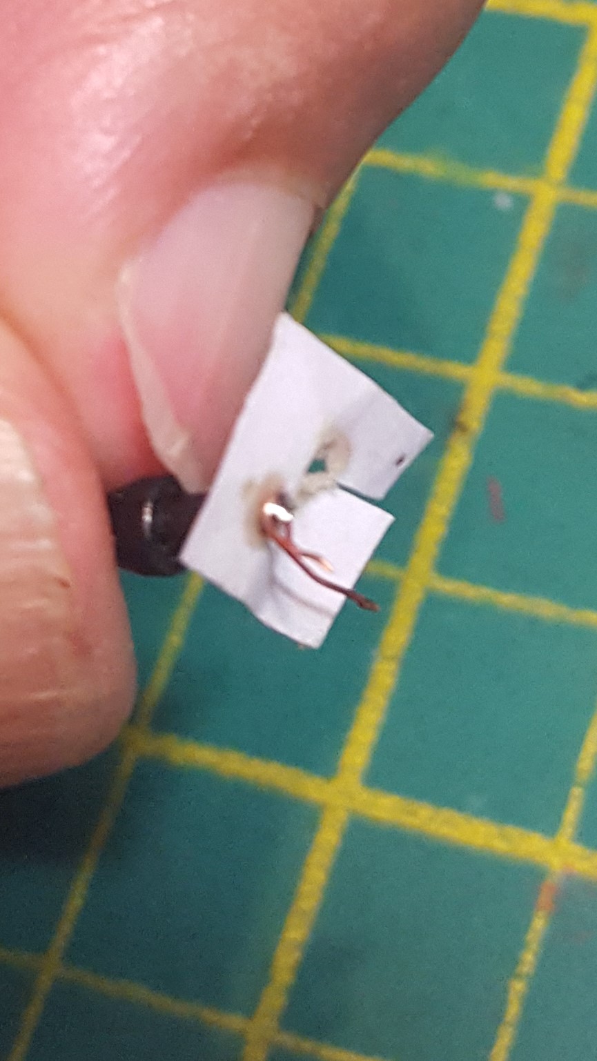 |
| using a piece of paper as a barrier to stop the solder from going where it shouldn't when soldering the thin wire to the buffer shank |
 |
| the wire soldered to the buffer shank before cleaning it up |
 |
| test fitting of the sugarcube speaker |
I used a sugar cube speaker and have glued it to the existing speaker tower as indicated in the above photo where I was testing for any interference to the bogie movement, pleased to say all worked well, but the speaker is glued to the speaker support over the bogie near the radiator, not the cab bogie where this photo is.
 |
| side on photo showing the sand pipes |
For those with an eye to detail may notice that the model sits slightly lower than a normal Eureka 40, this is courtesy of Craig who milled out the chassis for me, something which I think is well worth doing.
And now I only have to worry about weathering to finish it off.
The On Track 82 Class
As mentioned at the beginning of this post the On Track 82 is, I think, the easiest of the 4 to separate the headlights from the markers, and if wanted to it looks like one can easily control the ditch lights separately also. This is because the lights have their own wires from the main board to the lights / lightboard and so it's simply a matter of connecting the appropriate wire to their respective output on the decoder, no need to cut wires or traces.

My On Track 82 has a Loksound v4 decoder loaded with the appropriate sounds. Most who have used the loksound decoders know, that in the main, they only have 4 amplified functions and the remainder are non-amplified low power logic level functions that do not have enough power to drive LEDs thus I've used some MOSFETs as power amplifiers to boost the output of the F3 & F4 logic function logic, not my idea - there is data on the web (as an example This UK Website discusses MOSFETs, there are others) that explains things better than I can but I'll explain what I did below, one thing to be aware of is that some MOSFETs may not work (or at least did not work for me), I originally bought some N-Channel 702-7002MOSFETs but the markers were a constant dim or bright, were I wanted On or Off (ie. not On/Dim). After doing a bit more reading I bought some N-Channel SOT-23 Transistor IRLML2502 Mosfets which gave me the results I was after (ie. On/Off), I think the important thing is that the part Id. contains the letters 'IRLM' as that seems to mean they have a low draw.
As mentioned the Headlight functions, Fwd & Rvs, and Functions 1 & 2 have the capability to power LEDs without any further amplification, however Functions 3 & 4 are low power logic level outputs and do not deliver enough power to light the LEDs, I've also read that if a device (eg.LED or light globe) is connected directly to the logic level outputs that it can damage the decoder, but one can use MOSFETs to amplify the output and thus provide enough power so that the LED markers can be connected to the appropriate output.
 |
| 82 with loksound 4 fitted and sugarcube speaker |
The above photo is just a general overall view of the interior of the 82 with the decoder and sugar cube speaker fitted. The speaker is more or less under the exhaust grille.
 |
| Loksound 4 and sugarcube speaker |
 |
| TCS 21 pin board |
The above 2 photos show the Loksound 21pin decoder, and the TCS 21pin adapter(Part No. 21-HWM-5Pack) onto which the decoder is fitted, I cut a couple of grooves in the plastic block which supports the 21pins so that the grey and orange wires have a more or less direct route out.

The photo above is of the TCS 21pin board showing both sides, the outputs for F3 & F4 are the 2 pads on the underside of TCS board(the board on the left had side), as is the ground which needs to be used to power the MOSFET (amplifiers), you may notice that there are no solder pads to solder speaker wires to, I've simply soldered them to there respective pins and run them underneath the TCS board through to the speaker as shown below, the speaker wires are the two violet wires, they are soldered to pins 9 & 10 which are next to the blanked off index pin (pin 11), but please note that the TCS board does NOT have the index pin removed and I simply cut it off, the brown wire is soldered to the pad for Aux 3, the pink wire is soldered to the pad for Aux 4 and the black wire(s) is soldered to the ground pad.

These 3 wires (ie. the Brown Aux3, Pink Aux4 & Black Ground) are then connected to the MOSFET, one MOSFET per function, and then to their respective LED.
The MOSFET has 3 connections, namely
- The Gate (G) to which the wire from the decoder Auxilary Pad (Pink or Brown) is soldered to
- The Source (S) to which the wire from the decoder Ground Pad (Black) is soldered to
- The Drain (D) from which the wire to the LED is soldered to

And the below photo is the Mosfet wired up (Black wire from ground pad, Pink wire from Aux 4 and Yellow wire to marker light LED - but please note that this is looking from the bottom up rather than top down)

And the end result of this little experiment is white marker lights that are separately controlled to the headlights
 |
| Headlight Only |
 |
| Headlight and White Marker lights |
 |
| White Marker lights only |
 |
| Red Marker lights only |
To me, this sets off a bloody nice model.
I'll cover the 41 & 43 next time.
These are great tips, and I appreciate the extreme close-up pictures showing the PCB and wiring. Tnanks
ReplyDeleteThis comment has been removed by a blog administrator.
ReplyDelete