I started to write this blog post just after I had a meeting at my place way back in November 2016, and am only just finishing it off now, over a year later , I've hosted another couple of sessions of the modelling group I'm involved in since and have made minor progress on the layout. As part of getting the layout ready for a meeting I had back in November '16 I went back to the roundhouse (or at least the small part I have built of it), and I was very disappointed with what I saw, the dwarf brick walls (made from Styrene sheet and embossed Slaters brick and glued onto a 40thou base ) had warped and now had a distinct inwards lean,
partially due to the floor warping upwards at the outer edges which was probably due to not being in it's correct location and bedded down properly (it was just resting on the layout and so not held in place properly) and the floor had then over time bent/warped upwards on the edges, and even with placing the roundhouse base back into it's proper location and thus flattening the floor off, the walls still remained warped inwards.
The rail in the roundhouse was initially superglued which let go, so I re-glued the rail using solvent based Kwik contact and also spiked to help stay in place, nearly 2 years later later so far so good.
I've also made a few inspection pits for Mudgee & Liverpool Locos with thanks to Jeff Mullier who posted some plans of inspections pits on facebook & whilst I did not follow the plans to the letter they were very helpful. The pits where made from 40th (1mm) Styrene sheet
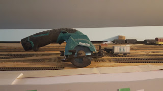
and fitted into a hole cut into the plywood to suit, I cut the hole with a Makita mini circular saw which has a thin blade and which is only about 3" Dia, I bought the saw sight unseen from a friend who works for Makita & when she bought it home for me my initial reaction was ohh bugger, what have I bought, at the time I thought it was it too small and would not see much use, but boy was I wrong, it's been a very useful addition to my bunch of tools and I have used it more than I thought I would have and has been very handy. Once I fitted the inspection pit into its place I then glued the rails in place using Kwik Grip and drilled holes to drive spikes into, so the rails are glued & spiked. Whilst I've made the inspection pits for Mudgee Loco, I have yet to fit them and will be using the small Makita circular saw to cut the baseboard to fit them - sure beats using a jigsaw.
Points are now controlled by the DCC system and can be changed from the Command Station throttles or the radio throttles, and will eventually be able to be controlled from push buttons on a control panel. I use TAM Valley Quadpic servo drivers which have an inbuilt DCC decoders & they allow individual addressing numbers/Ids upto 500 and 500 upwards are for macros, unfortunately my current version of the software my DCC system uses limits accessory decoder addresses to 99 whilst the upgrade I have, but am yet to fit, will allow upto 2148 addresses so I am (temporarily) using numbers 1 to 99 to address the points but once I have upgraded the system I will assigned the 100's for staging yard points, 200's for the lower level and 300's for the upper level, I then further refine it by assigning 100 to 130 for the Wyawang stage, leaving say 150 to 180 for Liverpool stage, then for lower level 200 - 230 for Liverpool & 250 to 280 for Wyawang, then 300 to 330 for Portland, 340-370 for Mudgee & 380 - 399 for Dunedoo, well at least thats the plan.
To assist myself,and others, to figure out what address is for what point, I made a number of control panels and drew the track layout using QCAD (a freebie CAD drawing system I found on the net) and numbered each point as well as highlighting what is the 'reverse' and the 'normal' throw of the points.
The drawing has been designed so that the TAM Valley push button circuit board's LEDs basically fits into the respective leg of the turnout it controls to indicate which direction the point is thrown.
This panel is for Wyawang West and cover the whole of that section (another covers the East side), and like the others I made at the time, was basically made as a temporary thing for a meeting that was being held and are not intended as the finished product, I also made a number of smaller ones (See the photos of Liverpool below) and taped them approximately in their correct position on the fascia board for individual points or small groups of points, more or less so I can get a feel for which method is preferable.
The nice thing about group meetings is the feedback that one gets and a few of the guys said they much prefer the smaller diagrams as they seemed easier to follow whereas the larger ones (like Wyawang West) where too much - though the larger ones may have been OK if there where LEDs installed to show which way the points where thrown (which the final control panels will have).
The Liverpool yard has also been finished, all droppers have been soldered & servo point motors installed and tested and the yard has 'shunted' just to make sure it all works.
Portland Cement works now has a crossover within the works because when looking and thinking about how the works where to function I never liked the fact that whilst a train could come in from Portland station, the loco had no way of being released, luckily I had a couple of spare points which I installed, the track at the end of the crossover is just long enough to release a 48, I'm happy with that because I don't envisage anything larger operating on the cement branch.
So next on the agenda was to make sure all the points worked as expected and to re-set the ones that needed it, and to then run a couple of test trains around before the guys arrived on the day, I'm pleased to say it worked OK & in the main the day went fairly well, though the Powerline 48, which had previously been used to test the layout and was still on the layout but not being operated, shorted out the system & when taken off the track the loco felt very warm/hot to the touch and would not run - I dismantled the loco & tested the motor by by-passing the decoder & the motor still spins, so I guess its a decoder issue which I understand is a common problem with the Powerline 48's & their factory fitted 'decoder', I may fit a spare decoder I think I have somewhere to see if the loco still works, if it does then I may install a better decoder and if not then this may end up being a dummy loco and does make me wonder whether it's worthwhile getting Powerline locos in the future.
Only thing really left now trackwise is to make the points for the Liverpool staging yard and to make the beyond Dunedoo stage, then to run the layout for a while to iron out the bugs (& I'm sure there will be some) and then I can start on the fun stuff - scenery.
In the weeks after the meeting I decided to have a go at kitbashing a Walthers 'flats' building based on their Geo. Roberts Printing kit into something resembling an Abattoir, the front and one side have used the kit parts, modified by infilling the windows with brickwork, whereas the rear and the far side where scratched using Walthers bricksheet which look very nice - I quite like them, though one needs to be aware that they are very fragile & break easily, I had to revert to using a razor saw to cut the sheets as using a knife led to the sheet snapping, and not along the cut line (I've had to glue a few back together) and trying to use the score & snap method is out of the question - certainly not like any styrene I've used in the past.
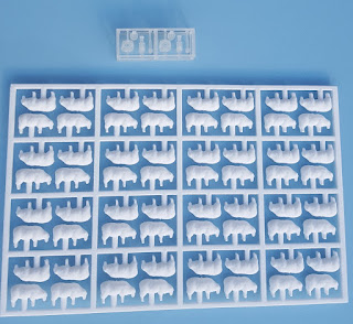
Shapeways recently had a free postage & 10% off sale, so I took advantage of that & bought some of Ray Pilgrims's sheep and catchpoint indicators - I'm nowhere near ready to use them, but they do look quite nice and won't go astray.
To wind this post up with, We had a pretty big occasion a couple of weeks back which is one of the reasons that the layout has not progressed as far as I had hoped, no complaints from me as this was a bloody great reason to put the layout in the background for a while and it was one of the biggest moments of my life walking this young lady down the aisle & welcoming her hubby to the family.


No comments:
Post a Comment